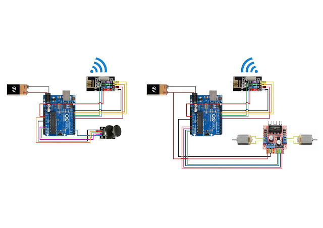
DC motor controlled by Joystick using Arduino & L298N Motor driver - Wireless Connection
Circuit Diagram: Required Components: Arduino uno/nano - 1 Nos Battery - 1 Nos DC Motor - 2 Nos L298N Motor Driver - 1 Nos Joystick - 1 Nos Transceiver - 2 Nos Program Code: Transmitter Code: #include <SPI.h> #include "RF24.h" int x_axis = A1; int y_axis = A2; int xvalue; int yvalue; int data[2]; RF24 radio(9,10); const uint64_t pipe=0xE8E8F0F0E1LL; void setup() { Serial.begin(9600); radio.begin(); radio.openWritingPipe(pipe); } void loop() {{ xvalue=analogRead(x_axis); xvalue=map(xvalue,0,1023,0,127); data[0]=xvalue; radio.write(data,1); } { yvalue=analogRead(y_axis); yvalue=map(yvalue,0,1023,128,255); data[0]=yvalue; radio.write(data,1); } Serial.println(xvalue); Serial.println(yvalue); } Receiver Code: #include <SPI.h> #include "RF24.h" const int motorforward = A1; const int motorbackward = A2; const int motorleft = A3; const int motorright = A4; int data[2]; RF24 radio(9,10); // CE,CS...


Sir Apne testing connections me 9 v provide Liya hai or actual circuit me Apne 5 v provide Liya hai
ReplyDeleteThis comment has been removed by the author.
DeleteHi, I am attempting to do the test for the Ht12-D and ht12-E. I am not getting anything in the LED's. I am getting voItage from pin 18 to pin 9 on the encoder, but no voltage from 18 to 9 on the decoder. I have switched out all components to check for bad components. Is there somewhere I could send a photo of my circuits to be checked?
ReplyDeleteHi
ReplyDeleteSir I have created same circuit but in my circuit Vt voltage is zero on the decoder IC what can be issue in my circuit?
in transmitter circuit there is some mistake written in Antenna circuit :
ReplyDeleteDATA
VCC
GND
ANT
please correct as
VCC
DATA
GND
ANT
kindly note and correct in your wiring diagram otherwise circuit will not be operative.
This comment has been removed by the author.
ReplyDeleteWhy reply delete please
ReplyDelete